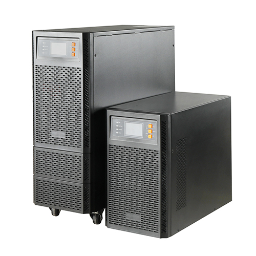
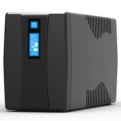
UPS power is an uninterruptible power supply (Uninterruptible Power Supply), which is an uninterruptible power supply with an energy storage device. It is mainly used to provide uninterrupted power supply to some devices that require high power stability.

When the mains input is normal, the UPS will stabilize the mains and supply it to the load. At this time, the UPS is an AC voltage stabilizer, and it also charges the battery inside the machine; when the mains is interrupted (accidental power failure) When the UPS is switched on, the UPS will immediately supply 220V AC power to the load by switching the DC power of the battery to the load, so that the load can maintain normal operation and protect the software and hardware of the load from damage. UPS devices usually provide protection against overvoltage or undervoltage.
How UPS power works
The basic structure of UPS power is a set of rectifiers and chargers that convert alternating current into direct current, and an inverter that converts direct current into alternating current. The battery stores energy and maintains a normal charging voltage when the alternating current is normally powered. When the mains power supply is interrupted, the battery immediately supplies power to the inverter to ensure the AC output voltage of the UPS power supply. The following diagrams illustrate the various working conditions of the UPS (take the online UPS power supply as an example).
(1) When the mains power is normally supplied within the range allowed by the UPS, as shown in Figure 2, the thick line depicts the flow of power energy.
(2) When the main power supply fails, that is, after the mains power supply is cut off, the power supply will be instantly switched to the inverter to provide energy, as shown in Figure 3.
(3) When the load is too large or the inverter in the power supply fails, the UPS will open the bypass and supply power directly from the main power supply.
Connection method
(1) A single UPS power supply can supply all loads. The connection diagram is as the schematic diagram of the system, and the connection method is relatively simple.
(2) The total load power requires two or more UPS power supplies, as shown in Figure 5, this connection method is called parallel connection without backup.
(3) The total capacity of two or more UPS power supplies is greater than the total load capacity, but the system must have more capacity than the total load capacity of one UPS power supply. When any one UPS power supply fails, the rest can still supply all load, as shown in Figure 6. This connection mode is called parallel backup mode.
(4) After the entire UPS power system fails, the utility power will disconnect the UPS power supply and directly connect the load without affecting the maintenance of the UPS power supply system. This circuit design is shown in Figure 7.

When there is no fault in the UPS power system, the maintenance switch is turned on, and the input switch and output switch are closed; when the UPS power system is faulty, the maintenance switch is closed, and the input switch and output switch are turned on. In this way, the normal work of the electrical load is ensured without affecting the online maintenance of the UPS power system failure.
 English
 Español
 Português
 русский
 français
 日本語
日本語
 Deutsch
 Tiếng Việt
 Italiano
 Nederlands
 ไทย
ไทย
 Polski
 한국어
한국어
 Svenska
 magyar
 Malay
Malay
 বাংলা
বাংলা
 Dansk
Dansk
 Suomi
Suomi
 हिन्दी
 Pilipino
 Türk
Türk
 Gaeilge
 عربى
عربى
 Indonesia
 norsk
norsk
 اردو
اردو
 čeština
 Ελληνικά
 Українська
 Javanese
 فارسی
فارسی
 தமிழ்
தமிழ்
 తెలుగు
 नेपाली
 Burmese
 български
 ລາວ
ລາວ
 Latine
 Қазақ
Қазақ
 Euskal
 Azərbaycan
 slovenský
 Македонски
 Lietuvos
 Eesti Keel
 Română
 Slovenski
 Српски
 Беларус


